Product Details
Product Introduction
Nepstech1550nm32 Port 22dbm High Power Optical Fiber Amplifier EYDFA with WDM
1. Product Application:
This manual applies to fiber amplifier. It mainly describes the performance characteristics, technical parameters, installation and debugging, common troubleshooting, and other related content of the product.In order to ensure that the equipment can be successfully installed and safely operated, please read this manual carefully before installing and debugging the equipment. And the installation and debugging should be strictly according to the specified steps on the manual to avoid unnecessary damage to equipment or accident harm to the operator. Any questions, please contact with us in time.
- ErYb Co-doped Fiber Amplifier is high end professional equipment, and its installation and debugging must be operated by special technician. Read this manual carefully before operating to avoid damage to equipment caused by fault operation or accident harm to the operator.
- While the fiber amplifier is working, there is an invisible laser beam from the optical output adapter on the front panel. Avoiding permanent harm to the body and eye, the optical output should not aim at the human body and human should not look directly at the optical output with the naked eye!
- Please make sure that the ground terminal of the case and power outlet has been reliably grounding before turning on the power (Grounding resistance should be <4Ω) to prevent the static damage the pump laser device and harm to human because of case charged.
- To ensure the equipment can work stable over a long time, in voltage unsteady or poor voltage wave region, it´s recommend to the customer that he equips special AC regulated power supply, or even AC uninterrupted power supply (UPS) system for conditional users. In the region with large temperature variation environment (The equipment's ideal work environment temperature is 25°C) or bad room environment, it´s recommend to the customer that he equips special air-condition system to improve the work environment.
Product photo show
Special Features
-
Application
- Single-mode fiber 1550amplification network
- FTTHnetwork
- CATVnetwork
- Long distance trunk network.FTTx PON, max working
wavelength: 1529.16~1563.86nm. - All kinds of SDH/PDH transmission system.
-
Performance Characteristics
- Built-in opticalFWDM,it can transmit broadband network and CATV together.
- Adopts ErYb Co-doped double-clad fiber technology;
- CATV input ports: 1 optional
- OLT input ports:4-32 optional
- Com Output ports: 4-32 optional;
- Optical output power: total output up to 15W(41dBm);
- Low noise figure: <6dB when input is 0dBm;
- Perfect network management interface, in line with standard SNMP network management;
- Intelligent temperature control system makes the power consumption lower;
-
Block Diagram
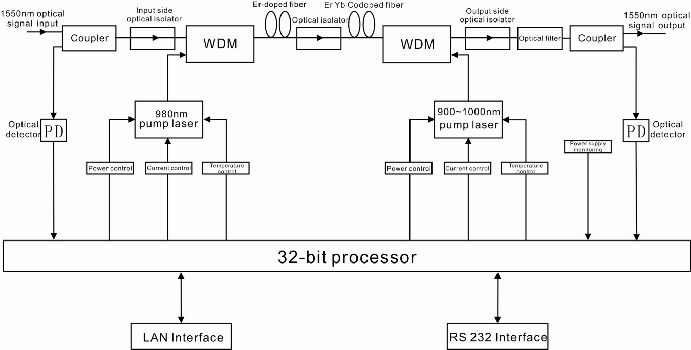
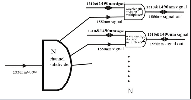
Internal integrated FWDM structure
Download Document
Technical parameters
4. Technical Parameter
4.1 Technical Parameter
|
Item |
Unit |
Technique parameters |
Remark |
|
|
Operating bandwidth |
nm |
1545 - 1565 |
||
|
Optical input power range |
dBm |
-3 - +10 |
Max range: -10-+10 |
|
|
Optical Switching time |
ms |
≤ 5 |
||
|
Maximum optical output power |
dBm |
41 |
||
|
Output power stability |
dBm |
±0.5 |
||
|
Noise figure |
dB |
≤ 6.0 |
Optical input power 0dBm, λ=1550nm |
|
|
Return loss |
Input |
dB |
≥ 45 |
|
|
Output |
dB |
≥ 45 |
||
|
Optical Connector Type |
CATV IN:SC/APC, PON:SC/PC OR LC/PC COM:SC/APC OR LC/APC |
|||
|
PON to COM port insertion loss |
≤ 1.0 |
dBm |
||
|
C/N |
dB |
≥ 50 |
Test condition according to GT/T 184-2002. |
|
|
C/CTB |
dB |
≥ 63 |
||
|
C/CSO |
dB |
≥ 63 |
||
|
Power supply voltage |
V |
A:AC100V - 260V (50 Hz~60Hz) B:DC48V(50 Hz~60Hz) C:DC12V(50 Hz~60Hz) |
||
|
Operating temperature range |
°C |
-10 - +42 |
||
|
Maximum operating relative humidity |
% |
Max 95% no condensation |
||
|
Maximum storage relative humidity |
% |
Max 95% no condensation |
||
|
Dimension |
mm |
483(L)×440(W)×88(H) |
||
4.2 Model and Power Comparison Table
|
Model |
Total output power dBm |
Output ports number |
Output power per port dBm |
ADD WDM |
|
EYA-4 -18 |
25 |
4 |
18 |
17 |
|
EYA-4 -19 |
26 |
4 |
19 |
18 |
|
EYA-4 -20 |
27 |
4 |
20 |
19 |
|
EYA-4 -21 |
28 |
4 |
21 |
20 |
|
EYA-4 -22 |
29 |
4 |
22 |
21 |
|
EYA-4 -23 |
30 |
4 |
23 |
22 |
|
EYA-4 -24 |
31 |
4 |
24 |
23 |
|
EYA-8 -15 |
25 |
8 |
15 |
14 |
|
EYA-8 -16 |
26 |
8 |
16 |
15 |
|
EYA-8 -17 |
27 |
8 |
17 |
16 |
|
EYA-8 -18 |
28 |
8 |
18 |
17 |
|
EYA-8 -19 |
29 |
8 |
19 |
18 |
|
EYA-8 -20 |
30 |
8 |
20 |
19 |
|
EYA-8 -21 |
31 |
8 |
21 |
20 |
|
EYA-8 -22 |
32 |
8 |
22 |
21 |
|
EYA-8 -23 |
34 |
8 |
23 |
22 |
|
EYA-16 -15 |
29 |
16 |
15 |
14 |
|
EYA-16 -16 |
30 |
16 |
16 |
15 |
|
EYA-16 -17 |
31 |
16 |
17 |
16 |
|
EYA-16 -18 |
32 |
16 |
18 |
17 |
|
EYA-16 -19 |
33 |
16 |
19 |
18 |
|
EYA-16 -20 |
34 |
16 |
20 |
19 |
|
EYA-16 -21 |
35 |
16 |
21 |
20 |
|
EYA-16 -22 |
36 |
16 |
22 |
21 |
|
EYA-32 -15 |
32 |
32 |
15 |
14 |
|
EYA-32 -16 |
33 |
32 |
16 |
15 |
|
EYA-32 -17 |
34 |
32 |
17 |
16 |
|
EYA-32 -18 |
35 |
32 |
18 |
17 |
|
EYA-32 -19 |
36 |
32 |
19 |
18 |
|
EYA-32 -20 |
37 |
32 |
20 |
19 |
|
EYA-32 -21 |
38 |
32 |
21 |
20 |
|
EYA-32 -22 |
39 |
32 |
22 |
21 |
|
EYA-32 -2 3 |
40 |
32 |
2 3 |
22 |
|
EYA-32 -2 4 |
41 |
32 |
2 4 |
2 3 |
From PON Port to COM Port have 1dBm insert loss& 1310nm and 1490nm.
5. External Function Description
5.1 Front Panel Description

Schematic diagram of the front panel
1) Power indicator: One switching power supply is working – yellow; two switching power supplies are working – green.
2) Optical input power indicator:This light turns on when the optical input power is > -10dBm.
3) Pump working status indicator: Red light means the pump is not working, but the machine parameters are normal; flashing red light means the machine has broken down, related fault reason see the alarm menu of the display menu; green light means the pump is working normal.
4) Optical output power indicator: This light turns on when the optical output power is > +10dBm.
5) 160×32 dot-matrix LCD screen: used to display all the parameters of the machine.
6) Display the exit or cancel key of the setup menu.
7) Display the up or increase key of the setup menu.
8) Display the down or decrease key of the setup menu.
9) Display the enter key of the setup menu.
10) Optical signal output: This interface is the optical signal output port of the device. The default connector type is SC/APC; the port number is 4-32 optional. Other specification requirements are specified by the customer.
Warning: There is an invisible laser beam from this port while working normal. So the port should not be aligned to the human body or the naked eye to avoid accidental injury.
11) Optical signal input: The default connector type is SC/APC. Other specification requirements are specified by the customer.
12) Pump laser switching key: used to control the working status of pump laser. “ON” means the pump laser is open and “OFF” means the pump laser is closed. Ensure the key is on “OFF” position before power on. After passing self-test, rotate the key to “ON” position according to the displayed message.
5.2 Rear Panel Description

Schematic diagram of the rear panel
- Fan outlet.
- RS232 interface: Used for configuring the network management parameters.
- LAN interface: correspond to IEEE802.3 10Base-T, used for network management.
- The AC 220V input port of power supply 1.
- The fuse of power supply 1.
- The switch of power supply 1.
- The AC220V input port of power supply 2.
- The fuse of power supply 2.
- The switch of power supply 2.
- Ground stud of the chassis: used for the connection of device and ground wire.
5.2.1 DC Power Module Introduction
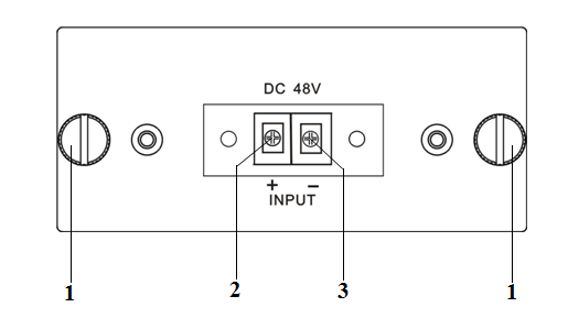
|
1 |
Mounting screws |
2 |
+ Positive terminal block |
3 |
- Negative terminal block |
6.1 Main Menu
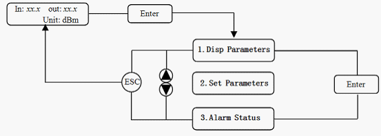
|
Name |
Display |
Description |
|
System Starting |
xxxxxxx |
Manufacturers’ logo |
|
xxxxxxx |
Equipment model |
|
|
xxxxxxx |
||
|
Suspend Page |
In: xx.xout: xx.x Unit: dBm |
Display the optical input / output power |
|
Main Page |
1.Disp Parameters |
Entry of parameter display menu |
|
2.Set Parameters |
Entry of parameter setup menu |
|
|
3.Alarm Status |
Entry of alarm information menu |
6.2 Display Menu
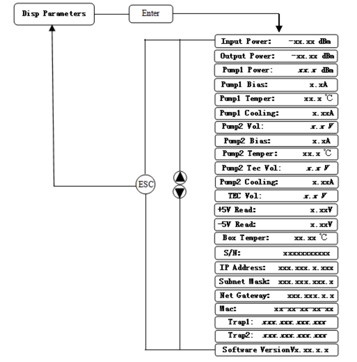
|
1.Disp Parameters |
Input Power: xx.x dBm |
Input power, accurate to 0.1 dBm |
|
Output Power: xx.x dBm |
Output power,accurate to 0.1 dBm |
|
|
Pump1 Power: xx.xdBm |
Power of pump1, accurate to 0.1 dBm |
|
|
Pump1 Bias: x.x A |
Bias current of pump1, accurate to 0.1 A |
|
|
Pump1 Temper: xx.x°C |
Temperature of pump1, accurate to0.1°C |
|
|
Pump1 Cooling: x.xx A |
Cooling current of pump1, accurate to 0.01 A |
|
|
Pump2 Vol: x.x V |
Drive voltage of pump2, accurate to 0.1 V |
|
|
Pump2 Bias: x.x A |
Bias current of pump2, accurate to 0.1 A |
|
|
* Pump2 Temper: xx.x ℃ |
Temperature of pump2, accurate to 0.1 °C |
|
|
* Pump2 Tec Vol: x.x V |
Cooling voltage of pump2, accurate to 0.1 V |
|
|
* Pump2 Cooling: x.xx A |
Cooling current of pump2, accurate to 0.01 A |
|
|
* TEC Vol: x.x V |
The first stage voltage of pump2 cooler, 0.1 V |
|
|
+5V Read: x.x V |
+5V power supply voltage , accurate to 0.1 V |
|
|
-5V Read: -x.x V |
-5V power supply voltage , accurate to 0.1 V |
|
|
Box Temper: xx.x°C |
Box temperature, accurate to0.1 °C |
|
|
S/N: xxxxxxxx |
Device serial number |
|
|
IP Address: xxx.xxx.xxx.xxx |
IP address |
|
|
Subnet Mask:xxx.xxx.xxx.xxx |
Subnet mask |
|
|
Net Gateway:xxx.xxx.xxx.xxx |
Gateway |
|
|
Mac: xxxxxxxxxxxx |
Physical address |
|
|
Trap1: xxx.xxx.xxx.xxx |
trap1 address |
|
|
Trap2: xxx.xxx.xxx.xxx |
trap2 address |
|
|
Software Version: Vx.xx.x.x |
Firmware version number |
The ultra high power output EDFA no the “*” menu.
6.3 Setup Menu
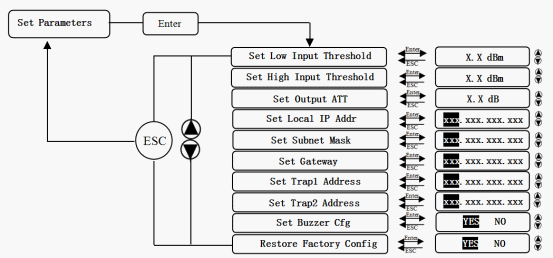
|
2.Set Parameters |
Set Low Input Threshold |
Set the low optical input power alarm threshold, range -3.0~10.0dBm |
|
Set High Input Threshold |
Set the high optical input power alarm threshold , range -3.0~10.0dBm |
|
|
*Set Output ATT |
Set the optical output power attenuation |
|
|
Set Local IP Addr |
Set IP address |
|
|
Set Subnet Mask |
Set subnet mask |
|
|
Set Gateway |
Set gateway |
|
|
Set Trap1 Address |
Set trap1 |
|
|
Set Trap2 Address |
Set trap2 |
|
|
Set Buzzer cfg |
Set the switch of beeper |
|
|
Restore Factory config |
Restore the factory configurationset content as shown above |
The ultra-high-power output EDFA no the “*” menu.
6.4 Warning menu
|
3.Alarm Status
|
Input Status: xxx |
xxx= LOLOW: |
|
|
xxx= LOW: |
Low optical input power alarm |
||
|
xxx= HIGH: |
High optical input power alarm |
||
|
xxx= HIHIGH: |
Very high optical input power alarm |
||
|
Output Status: xxx |
xxx= LOLOW: |
Very low optical output power alarm |
|
|
xxx= LOW: |
Low optical output power alarm |
||
|
xxx= HIGH: |
High optical output power alarm |
||
|
xxx= HIHIGH: |
Very high optical output power alarm |
||
|
Pumpx Power: xxx |
xxx= LOLOW: |
Very low power of pump x alarm |
|
|
xxx= LOW: |
Low power of pump x alarm |
||
|
xxx= HIGH: |
High power of pump x alarm |
||
|
xxx= HIHIGH: |
Very high power of pump x alarm |
||
|
Pumpx Bias: xxx |
xxx= LOLOW: |
Very low bias current of pump x alarm |
|
|
xxx= LOW: |
Low bias current of pump x alarm |
||
|
xxx= HIGH: |
High bias current of pump x alarm |
||
|
xxx= HIHIGH: |
Very high bias current of pump x alarm |
||
|
Pumpx Temper: xxx |
xxx= LOLOW: |
Very low temperature of pump x alarm |
|
|
xxx= LOW: |
Low temperature of pump x alarm |
||
|
xxx= HIGH: |
High temperature of pump x alarm |
||
|
xxx= HIHIGH: |
Very high temperature of pump x alarm |
||
|
Pumpx Tec: xxx |
xxx= LOLOW: |
Very low cooling current of pump x alarm |
|
|
xxx= LOW: |
Low cooling current of pump x alarm |
||
|
xxx= HIGH: |
High cooling current of pump x alarm |
||
|
xxx= HIHIGH: |
Very high cooling current of pump x alarm |
||
|
+5V Status: xxx |
xxx= LOLOW: |
Very low +5V DC power supply alarm |
|
|
xxx= LOW: |
Low +5V DC power supply alarm |
||
|
xxx= HIGH: |
High +5V DC power supply alarm |
||
|
xxx= HIHIGH: |
Very high +5V DC power supply alarm |
||
|
-5V Status: xxx |
xxx= LOLOW: |
Very low -5V DC power supply alarm |
|
|
xxx= LOW: |
Low -5V DC power supply alarm |
||
|
xxx= HIGH: |
High -5V DC power supply alarm |
||
|
xxx= HIHIGH: |
Very high -5V DC power supply alarm |
||
|
Device Temper: xxx |
xxx= LOLOW: |
Very low chassis temperature alarm |
|
|
xxx= LOW: |
Low chassis temperature alarm |
||
|
xxx= HIGH: |
High chassis temperature alarm |
||
|
xxx= HIHIGH: |
Very high chassis temperature alarm |
6.4 Warning menu
|
|
xxx= LOW: |
Optical switch Low input power alarm |
|
|
xxx= HIGH: |
Optical switch High input power alarm |
||
|
B Input Optical: xxx |
xxx= LOW: |
Optical switch Low input power alarm |
|
|
xxx= HIGH: |
Optical switch High input power alarm |
||
|
AInput RF: xxx |
xxx= LOW: |
Optical switch Low input RF alarm |
|
|
xxx= HIGH: |
Optical switch High input RF alarm |
||
|
B Input RF: xxx |
xxx= LOW: |
Optical switch Low input power alarm |
|
|
xxx= HIGH: |
Optical switch High input power alarm |
||
|
Input Status: xxx |
xxx= LOW: |
EdfaLow optical input power alarm |
|
|
xxx= HIGH: |
EdfaHigh optical input power alarm |
||
|
Output Status: xxx |
xxx= LOW: |
Low optical output power alarm |
|
|
xxx= HIGH: |
High optical output power alarm |
||
|
Pumpx Bias: xxx |
xxx= LOW: |
Low bias current of pump x alarm |
|
|
xxx= HIGH: |
High bias current of pump x alarm |
||
|
Pumpx Temper: xxx |
xxx= LOW: |
Low temperature of pump x alarm |
|
|
xxx= HIGH: |
High temperature of pump x alarm |
||
|
Pumpx Tec: xxx |
xxx= LOW: |
Low cooling current of pump x alarm |
|
|
xxx= HIGH: |
High cooling current of pump x alarm |
||
|
+5V Status: xxx |
xxx= LOW: |
Low +5V DC power supply alarm |
|
|
xxx= HIGH: |
High +5V DC power supply alarm |
||
|
-5V Status: xxx |
xxx= LOW: |
Low -5V DC power supply alarm |
|
|
xxx= HIGH: |
High -5V DC power supply alarm |
7. Communication Setup Descriptions
7.1Communication Interface Description
1. RS232 communication interface
Adopt DB9 standard connector, the pin definitions as follow:

|
1: No Connect |
2: TX |
3: RX |
|
4: No Connect |
5: GND |
6: No Connect |
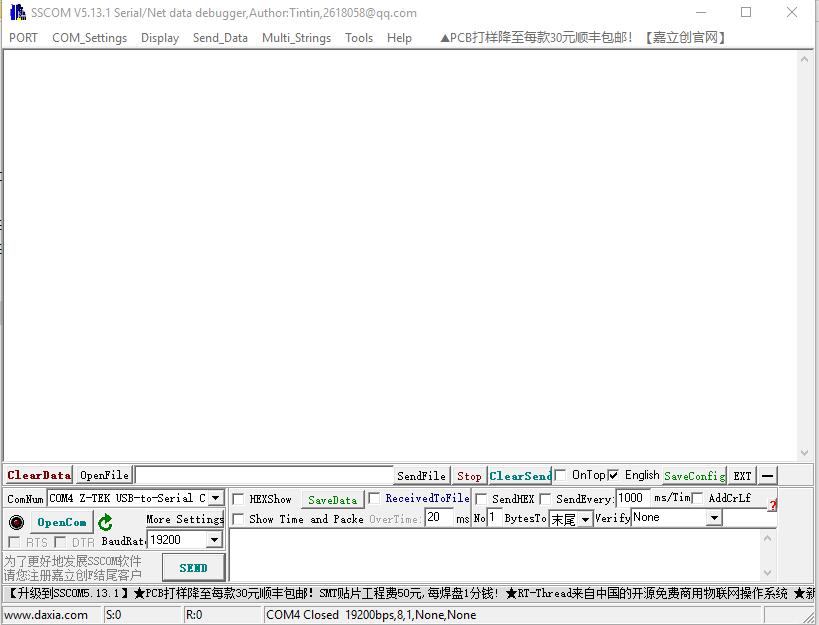
The serial communication uses the sscom App, bit and the baud rate is19200.
2.2) LAN communication interface
Adopt RJ45 standard connector, the pin definitions as follow:
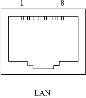
|
1: TX+ |
2: TX- |
3: RX+ |
|
4: No Connect |
5: No Connect |
6: RX- |
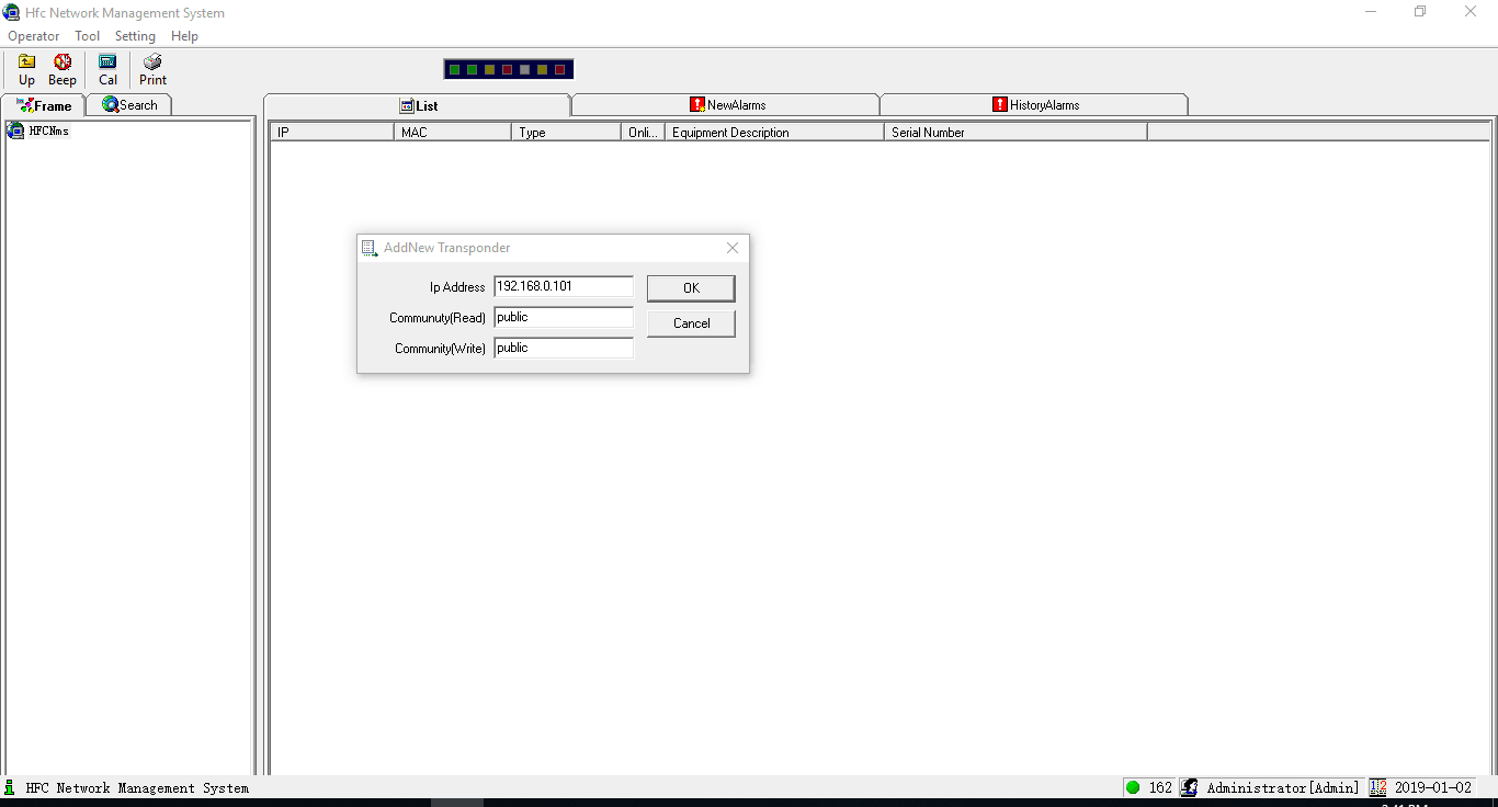
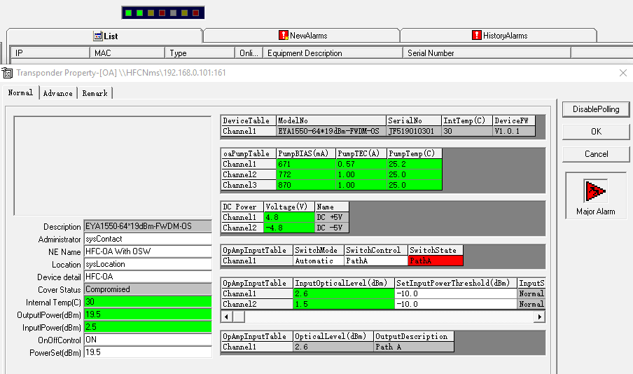
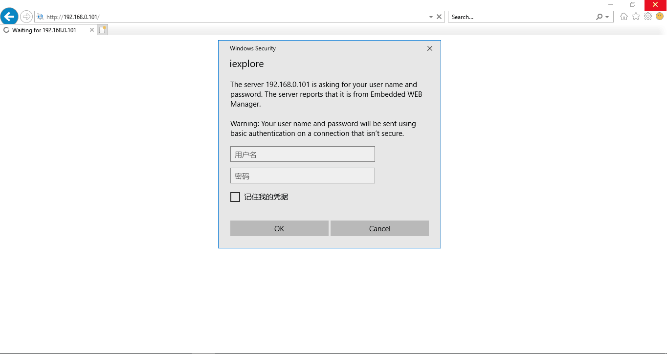
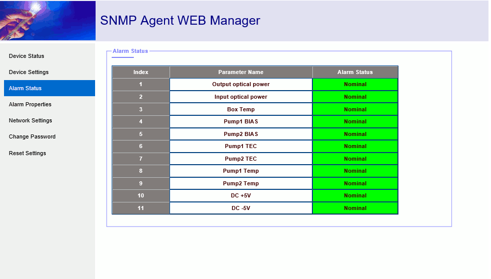
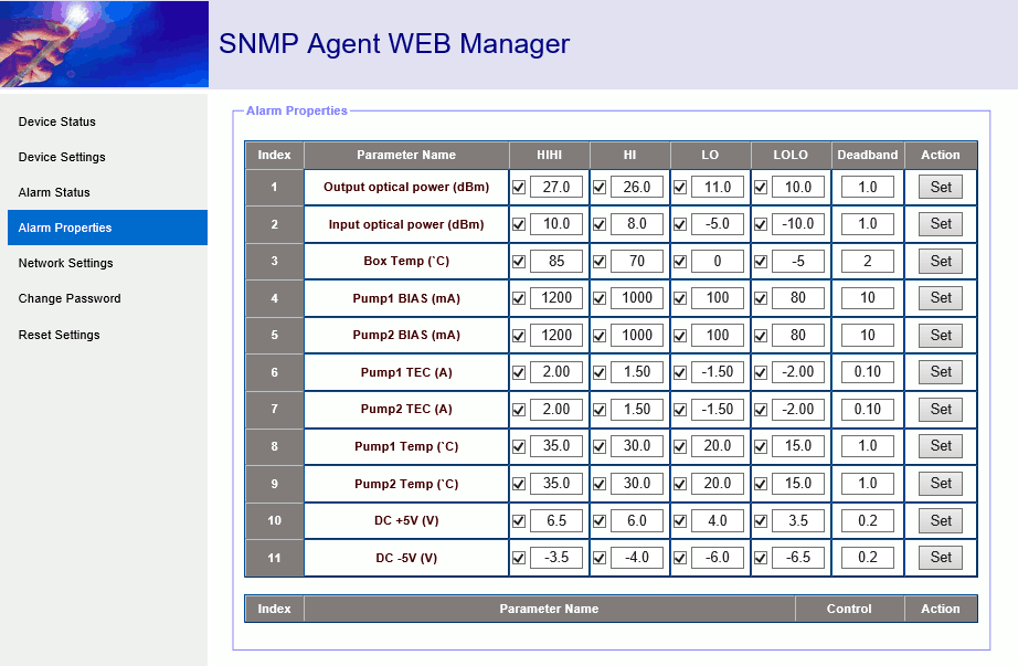
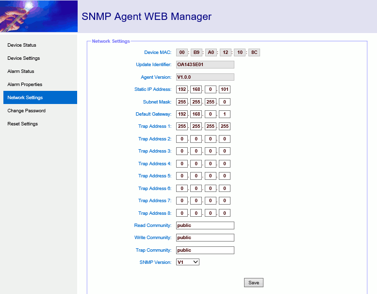
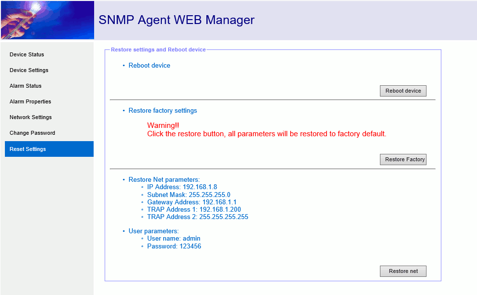
7.2.2 Support web browsing SNMP function
Username:Admin Password:123456
Device Status
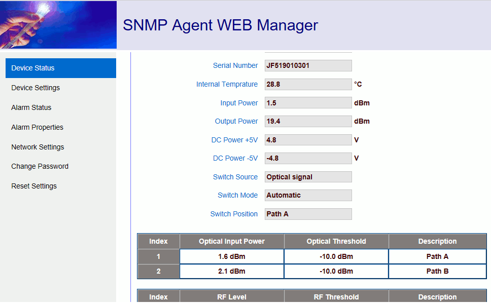
Device Settings:
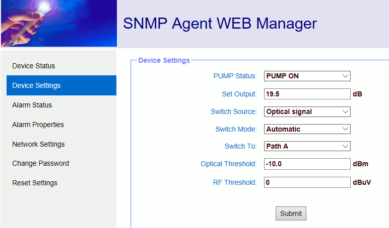
Alarm Status
Alarm Properties
Network Settings
Change Password
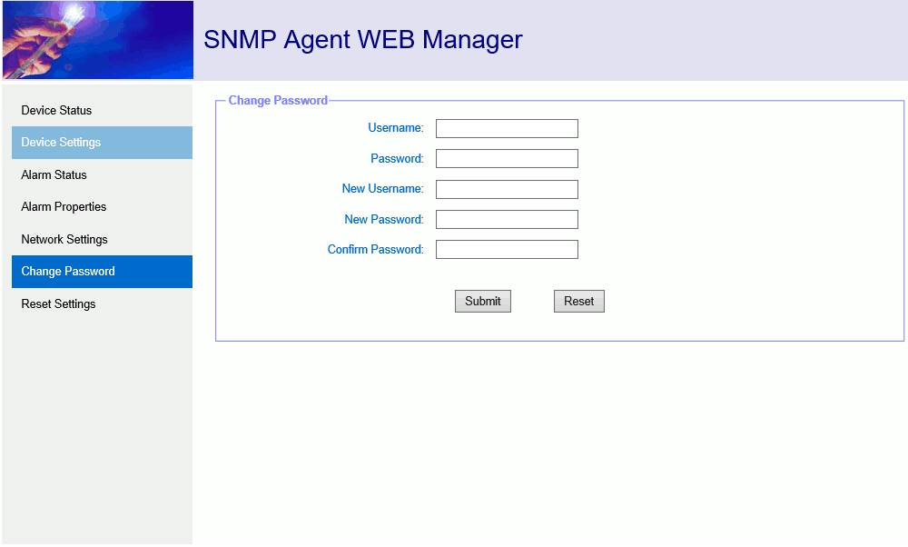
Reset Settings
8. Installation debugging
8.1Unpack and Check
- Insure the package is not defaced. If it has any damage or water mark, please contact local agency or carrier.
- After unpacking, check equipments and accessories according to package list. Any question, please contact local agency or our company.
- If you think the equipment has been damaged, please don't electrify to avoid worse damage. Please contact local agency or our company in time.
8.2 Instruments and tools
- An optical power meter;
- A digital multimeter;
- A standard optical fiber test jumper (SC/APC);
- Some absolute alcohol and medical cotton wool;
8.3 Installation steps
- Before installing the equipment, please read the <User's manual> carefully and install the equipment according to the <User's manual>.
Note: For the man-made damage and other all consequence caused by error installation that not according to the <User's manual>, we will not be responsible and will not supply free warranty. - Take out the device from the box; fix it to the rack and reliably grounding. (The grounding resistance must be < 4Ω).
- Use the digital multimeter to check the supply voltage, make sure the supply voltage comply with the requirements and the switch key is on the “OFF” position. Then connect the power supply.
- Input the optical signal according to the display message. Turn the switch key to the “ON” position and observe the front panel LED status. After the pump working status indicator turn into green, the device is working normal. Then press the menu button on the front panel to check the working parameters.
- Connect the optical power meter to the optical signal output end by the standard optical fiber test jumper, then measure the optical output power. Affirm the measured optical output power and the displayed power are the same and have reached the nominal value. (Affirm the optical power meter is on 1550nm wavelength test position; the optical fiber test jumper is the matched one and on the connector surface has no pollution.) Remove the standard optical fiber test jumper and optical power meter; connect the device to the network. So far, the device has been completely installed and debugged.
9. Clean and maintenance method of the optical fiber active connector
In many times, we consider the decline of the optical power as the equipment faults, but actually it may be caused by that the optical fiber connector was polluted by dust or dirt. Inspect the fiber connector, component, or bulkhead with a fiberscope. If the connector is dirty, clean it with a cleaning technique following these steps:
- Turn off the device power supply and carefully pull off the optical fiber connector from the adapter.
- Wash carefully with good quality lens wiping paper and medical absorbent alcohol cotton. If use the medical absorbent alcohol cotton, still need to wait 1~2 minutes after wash, let the connector surface dry in the air.
- Cleaned optical connector should be connected to optical power meter to measure optical output power to affirm whether it has been cleaned up.
- When connect the cleaned optical connector back to adapter, should notice to make force appropriate to avoid china tube in the adapter crack.
- If the optical output power is not normal after cleaning, should pull off the adapter and clean the other connector. If the optical power still low after cleaning, the adapter may be polluted, clean it. (Note: Be carefully when pull off the adapter to avoid hurting inside fiber.)
- Use compressed air or degrease alcohol cotton to wash the adapter carefully. When use compressed air, the muzzle aims at china tube of the adapter, clean the china tube with compressed air. When use degrease alcohol cotton, insert directions need be consistent, otherwise can’t reach a good clean effect.
- In the process of clean the active optical fiber connector, you should avoid direct shining at eye, which will cause permanence burn!!!!
- Use proper energy to install the active optical connector, or the ceramic tape in the adaptor will lead to break. Once the ceramic tape is broken, the optical output power will decrease rapidly. And turn the active optical fiber connector slightly, the optical output power changes obviously.
- Please operate the optical fiber under the condition of shut off the pump laser. Or the high output power will lead to burn the joint of the optical output fiber, which will cause the output power decrease.


